BIOS
Main Page
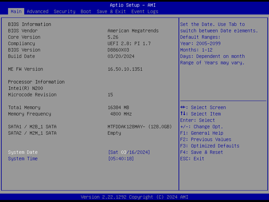
The Main Page provides an overview of system-level information. All fields are display-only and cannot be modified:
BIOS Vendor: American Megatrends
Core Version: 5.26
Compliancy: UEFI 2.8 ; PI 1.7
BIOS Version: Displays the version of the BIOS
Build Date: Shows the BIOS build date
ME FW Version: Displays the Management Engine firmware version
Processor Information: Displays the installed CPU brand
Microcode Revision: Displays the CPU microcode revision
Total Memory: Shows the installed memory size
Memory Frequency: Displays the memory frequency
SATA1 / M2B_1 SATA: Lists the installed SATA device model and size
SATA2 / M2M_1 SATA: Lists the installed SATA device model and size
System Date & Time
The System Date & Time fields allow configuring the system’s real-time clock:
System Date
Format:
[Www mm/dd/yyyy]Www: Day of the week (Mon–Sun)mm: Month (1–12)dd: Day (1–31)yyyy: Year (2005–2099)Use Tab to switch between elements
System Time
Format:
[hh:mm:ss]hh: Hours (0–23)mm: Minutes (0–59)ss: Seconds (0–59)Use Tab to switch between elements
Advanced Page
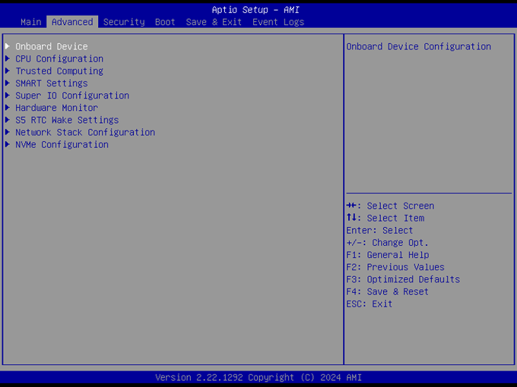
The Advanced Page gives you access to configuration menus for detailed system tuning and hardware settings.
Advanced Configuration Options
Onboard Device Configuration – Press Enter to access onboard device settings
CPU Configuration – Press Enter to configure CPU-related features
Trusted Computing – Press Enter to access TPM settings
SMART Settings – Press Enter to configure system SMART behavior
Super IO Configuration – Press Enter to configure Super IO chip parameters
Hardware Monitor – Press Enter to view hardware monitoring status
S5 RTC Wake Settings – Press Enter to enable or disable RTC wake from S5 state
Network Stack Configuration – Press Enter to manage network stack settings
NVMe Configuration – Press Enter to view NVMe device options
Onboard Device Configuration
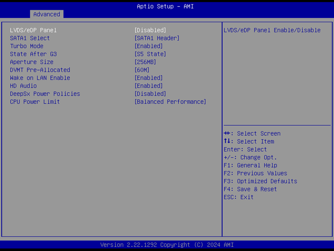
The Onboard Device Configuration menu allows you to enable or disable onboard components and adjust device-specific behavior.
Device Settings
LVDS/eDP Panel
Default:
DisabledOptions:
Enabled,DisabledEnables or disables the LVDS/eDP panel output.
SATA1 Select
Default:
SATA1 HeaderOptions:
M2B SATA_PCIE Slot,SATA1 HeaderSelects the SATA1 device source.
Turbo Mode
Default:
EnabledOptions:
Enabled,DisabledEnables or disables the CPU’s Turbo Boost feature.
State After G3
Default:
S5 StateOptions:
S0 State,S5 StateDetermines the system power state after power is restored following a G3 (mechanical off) state.
Aperture Size
Default:
256MBOptions:
128MB,256MB,512MB,1024MBSets the graphics aperture size.
Note: Selecting aperture sizes above 2048MB enables automatic MMIO BIOS assignment. To use this feature, disable CSM Support.
DVMT Pre-Allocated
Default:
60MOptions:
32M,36M,40M,44M,48M,52M,56M,60M,64M,96M,128M,160M,32M/F7Sets fixed graphics memory size (DVMT 5.0) used by the internal graphics device.
Wake on LAN Enable
Default:
EnabledOptions:
Enabled,DisabledAllows the system to be powered on remotely via the LAN.
HD Audio
Default:
EnabledOptions:
Enabled,DisabledControls detection of the HD-Audio device.
Enabled: HDA always on
Disabled: HDA always off
DeepSx Power Policies
Default:
DisabledOptions:
Disabled,Enabled in S4-S5Configures DeepSx low-power mode behavior in specific sleep states.
CPU Power Limit
Default:
Balanced PerformanceOptions:
Maximum Performance,Balanced Performance,Power SaverSets CPU TDP configuration:
Maximum Performance: Uses max CPU TDP based on SKU
Balanced Performance: Limits TDP to 10W
Power Saver: Limits TDP to 6W (N97 only)
CPU Configuration
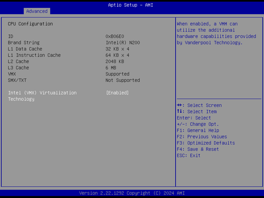
The CPU Configuration page displays processor-related information and supports virtualization settings. Most fields are read-only and cannot be modified.
CPU Details
ID
Displays the CPU signature
Not selectable
Brand String
Displays the CPU brand/model
Not selectable
L1 Data Cache
Shows L1 data cache information
Not selectable
L1 Instruction Cache
Shows L1 instruction cache information
Not selectable
L2 Cache
Shows L2 cache information
Not selectable
L3 Cache
Shows L3 cache information
Not selectable
VMX
Displays whether Virtual Machine Extensions are supported
Not selectable
SMX/TXT
Displays whether Safer Mode Extensions / Trusted Execution Technology is supported
Not selectable
Virtualization Setting
Intel® Virtualization Technology (VMX)
Default:
EnabledOptions:
Enabled,DisabledWhen enabled, virtualization-based software (VMM) can utilize additional hardware features provided by Intel® VT-x (Vanderpool Technology).
Trusted Computing
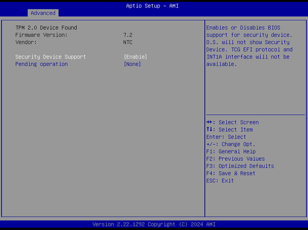
The Trusted Computing menu manages settings related to TPM (Trusted Platform Module) and BIOS-level hardware security.
TPM Information
Firmware Version
Displays the installed TPM module firmware version
Not selectable
Vendor
Shows the TPM vendor name
Not selectable
TPM Configuration
Security Device Support
Default:
EnabledOptions:
Enabled,DisabledEnables or disables BIOS-level support for the TPM device.
Note: If disabled, TCG EFI protocol and INT1A interface will not be available, and the OS will not detect the security device.
Pending Operation
Default:
NoneOptions:
None,TPM ClearSchedules a TPM operation.
Note: The system will reboot during restart to apply the change.
SMART Settings
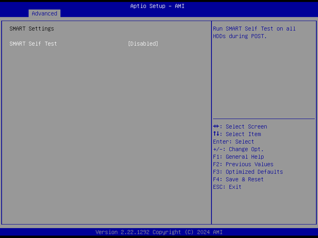
The SMART Settings menu allows configuration of SMART (Self-Monitoring, Analysis, and Reporting Technology) for storage health monitoring.
SMART Self Test
Default:
DisabledOptions:
Enabled,DisabledEnables SMART self-tests on all connected hard disk drives (HDDs) during POST (Power-On Self-Test).
Super IO Configuration
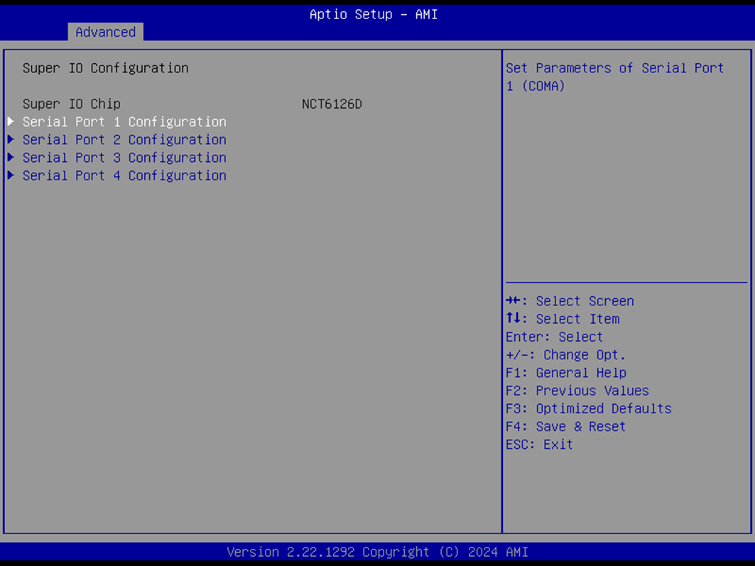
The Super IO Configuration menu provides access to settings for the system’s serial ports.
Serial Port Configuration
Serial Port 1 Configuration
Interface: COMA
Press Enter to access configuration submenu for Serial Port 1
Serial Port 2 Configuration
Interface: COMB
Press Enter to access configuration submenu for Serial Port 2
Serial Port 3 Configuration
Interface: COMC
Press Enter to access configuration submenu for Serial Port 3
Serial Port 4 Configuration
Interface: COMD
Press Enter to access configuration submenu for Serial Port 4
Serial Port 1 Configuration
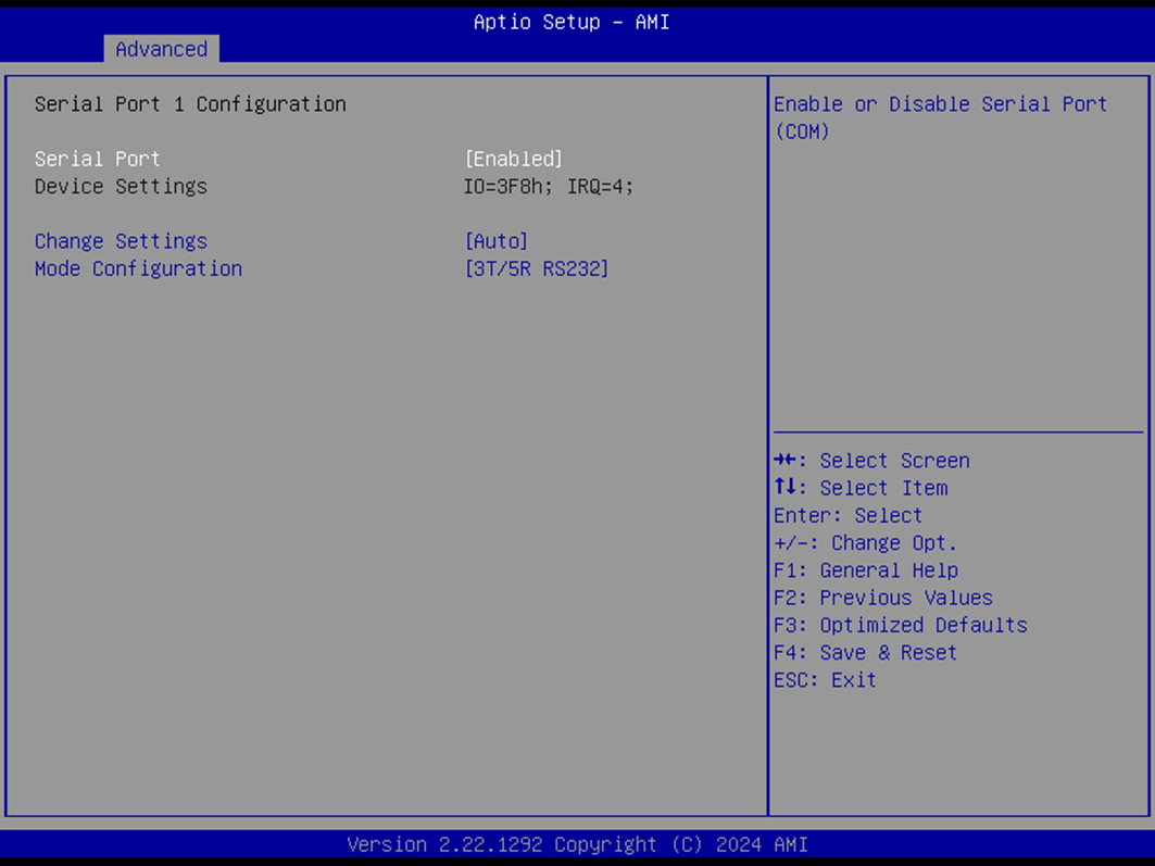
This section configures Serial Port 1 (COMA), including enabling/disabling the port, assigning address/IRQ, and setting the operating mode.
Serial Port
Default:
EnabledOptions:
Enabled,DisabledEnables or disables the serial port (COMA).
Device Settings
Displays Super IO COM1 address and IRQ
Not selectable
Change Settings
Default:
AutoOptions:
AutoIO=3F8h; IRQ=4IO=3F8h; IRQ=3,4,5,6,7,9,10,11,12IO=2F8h; IRQ=3,4,5,6,7,9,10,11,12IO=3E8h; IRQ=3,4,5,6,7,9,10,11,12IO=2E8h; IRQ=3,4,5,6,7,9,10,11,12
Allows selecting optimal COM1 settings manually or automatically.
Mode Configuration
Default:
3T/5R RS232Options:
1T/1R RS4223T/5R RS2321T/1R RS485 TX ENABLE Low Active1T/1R RS422 with termination resistor1T/1R RS485 with termination resistor TX ENABLE Low Active
Configures the serial port communication mode (RS232/RS422/RS485).
Serial Port 2 Configuration
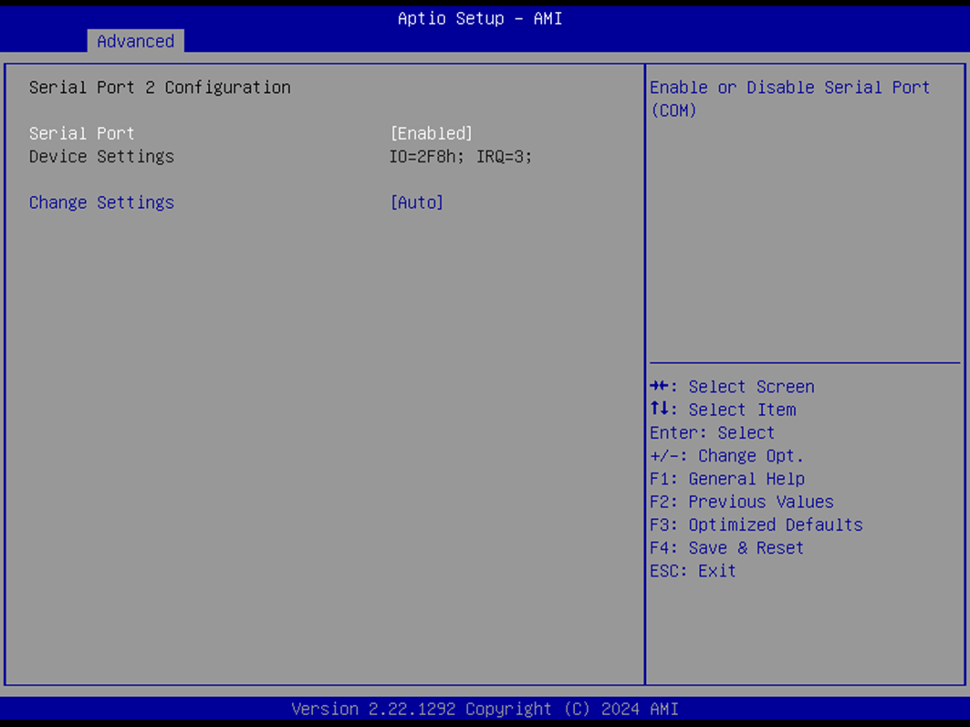
This section configures Serial Port 2 (COMB).
Serial Port
Default:
EnabledOptions:
Enabled,DisabledEnables or disables the serial port (COMB).
Device Settings
Displays Super IO COM2 address and IRQ
Not selectable
Change Settings
Default:
AutoOptions:
AutoIO=2F8h; IRQ=3IO=3F8h; IRQ=3,4,5,6,7,9,10,11,12IO=2F8h; IRQ=3,4,5,6,7,9,10,11,12IO=3E8h; IRQ=3,4,5,6,7,9,10,11,12IO=2E8h; IRQ=3,4,5,6,7,9,10,11,12
Allows selecting optimal COM2 settings manually or automatically.
Serial Port 3 Configuration

This section configures Serial Port 3 (COMC).
Serial Port
Default:
EnabledOptions:
Enabled,DisabledEnables or disables the serial port (COMC).
Device Settings
Displays Super IO COM3 address and IRQ
Not selectable
Change Settings
Default:
AutoOptions:
AutoIO=3E8h; IRQ=7IO=3E8h; IRQ=3,4,5,6,7,9,10,11,12IO=2E8h; IRQ=3,4,5,6,7,9,10,11,12IO=220h; IRQ=3,4,5,6,7,9,10,11,12IO=228h; IRQ=3,4,5,6,7,9,10,11,12
Allows selecting optimal COM3 settings manually or automatically.
Serial Port 4 Configuration
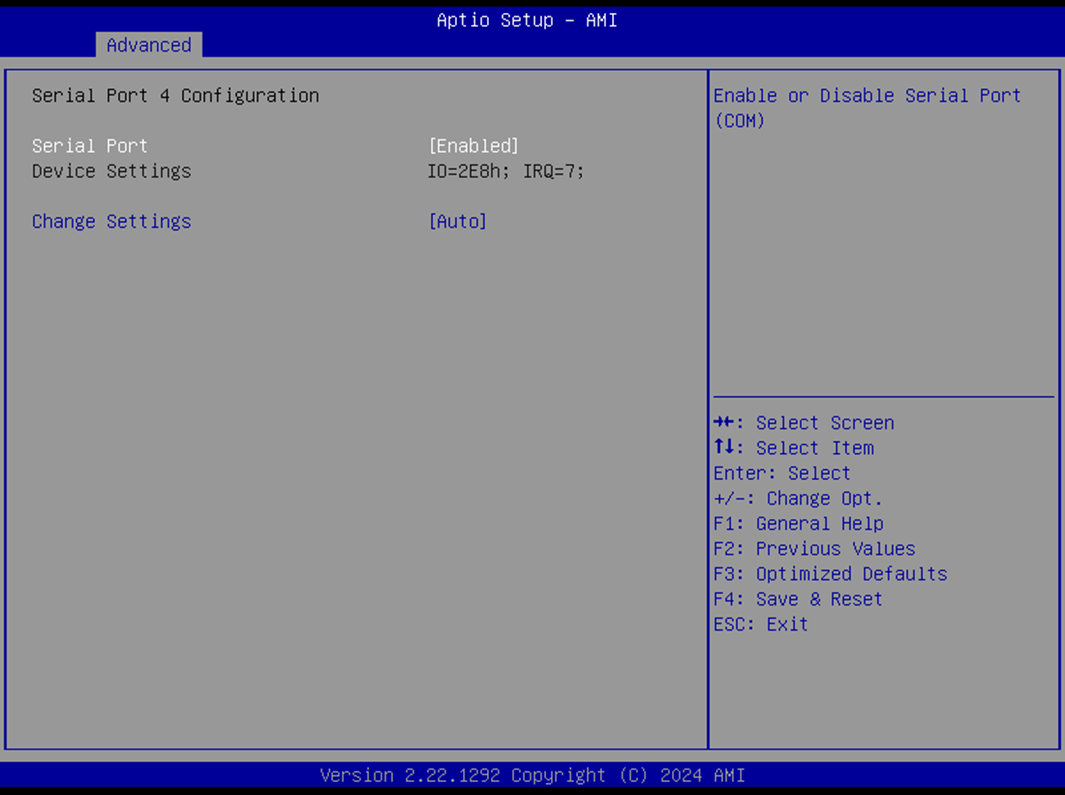
This section configures Serial Port 4 (COMD).
Serial Port
Default:
EnabledOptions:
Enabled,DisabledEnables or disables the serial port (COMD).
Device Settings
Displays Super IO COM4 address and IRQ
Not selectable
Change Settings
Default:
AutoOptions:
AutoIO=2E8h; IRQ=7IO=3E8h; IRQ=3,4,5,6,7,9,10,11,12IO=2E8h; IRQ=3,4,5,6,7,9,10,11,12IO=220h; IRQ=3,4,5,6,7,9,10,11,12IO=228h; IRQ=3,4,5,6,7,9,10,11,12
Allows selecting optimal COM4 settings manually or automatically.
Hardware Monitor
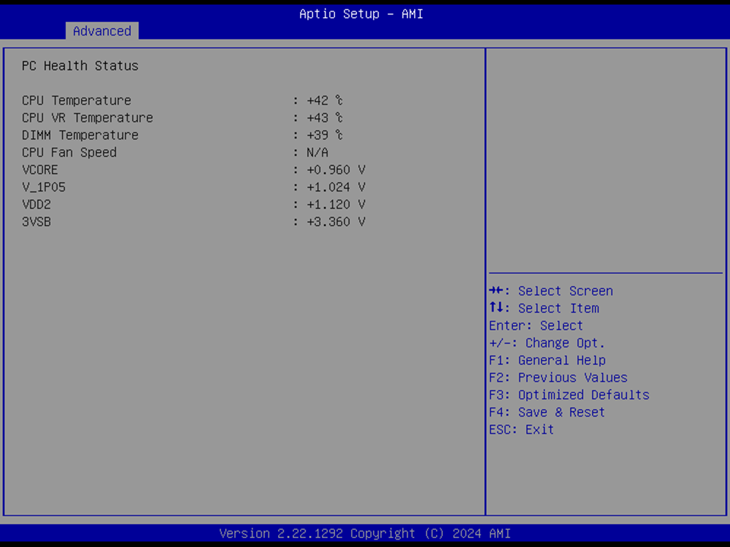
The Hardware Monitor page displays real-time system temperature, fan, and voltage information. All fields are read-only and intended for system diagnostics.
Sensor Readings
Type |
Range |
|---|---|
CPU Temperature |
-20°C to Processor TjMax |
CPU VR Temperature |
-20°C to 120°C |
DIMM Temperature |
-20°C to 120°C |
CPU Fan Speed |
0 RPM (minimum failure threshold) – No upper RPM limit |
VCORE |
0 V to 1.72 V |
V_1P05 |
0.9975 V to 1.1025 V |
VDD2 |
1.045 V to 1.155 V |
3VSB |
3.135 V to 3.465 V |
Note: Fan speed and voltage thresholds are system- and sensor-dependent. RPM reading of 0 indicates a fan failure condition.
S5 RTC Wake Settings
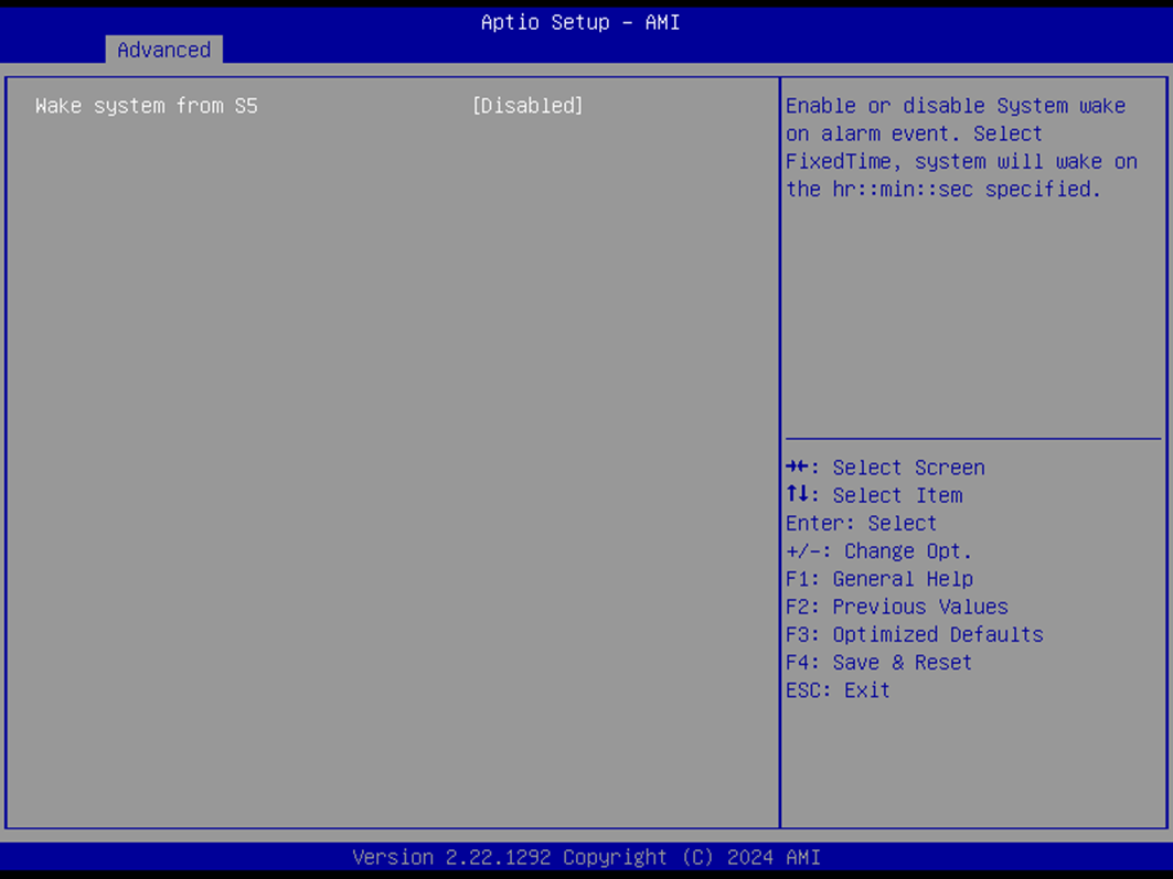
The S5 RTC Wake Settings menu configures automatic system wake-up behavior from the S5 (Soft Off) state.
Wake System from S5
Default:
DisabledOptions:
Disabled,Fixed TimeEnables the system to wake at a defined time from S5 state.
Wake Up Hour (Visible when Fixed Time is selected)
Default:
0Range:
0–23Sets the hour of wake-up. (e.g.,
3= 3 AM,15= 3 PM)
Wake Up Minute (Visible when Fixed Time is selected)
Default:
0Range:
0–59Sets the minute of wake-up.
Wake Up Second (Visible when Fixed Time is selected)
Default:
0Range:
0–59Sets the second of wake-up.
Network Stack Configuration
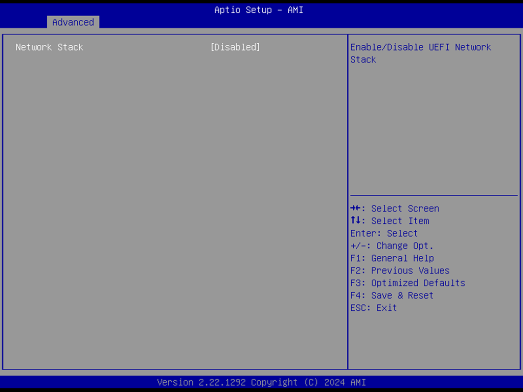
This section allows configuring the UEFI network stack and related PXE boot options.
Network Stack
Default:
DisabledOptions:
Enabled,DisabledEnables or disables the UEFI network stack.
IPv4 PXE Support (Available when Network Stack is Enabled)
Default:
DisabledOptions:
Enabled,DisabledEnables IPv4 PXE boot support.
IPv6 PXE Support (Available when Network Stack is Enabled)
Default:
DisabledOptions:
Enabled,DisabledEnables IPv6 PXE boot support.
NVMe Configuration
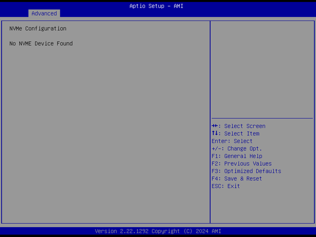
The NVMe Configuration page provides access to settings and information related to connected NVMe devices.
(Device)
Press Enter to view device details and configuration sub-menu.
Security Page
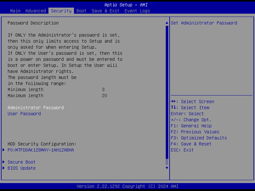
The Security Page allows users to configure BIOS access protection, disk security, secure boot, and firmware update options.
Security Options
Administrator Password
Set or modify the administrator password to control access to BIOS settings.
User Password
Set or modify a user-level password for limited access.
HDD Security Drive
Opens the HDD security configuration menu for password protection on specific drives.
Press Enter to access submenu.
Secure Boot
Opens the Secure Boot configuration menu for key and policy management.
Press Enter to access submenu.
BIOS Update
Launches the BIOS update utility.
Press Enter to access submenu.
HDD Security
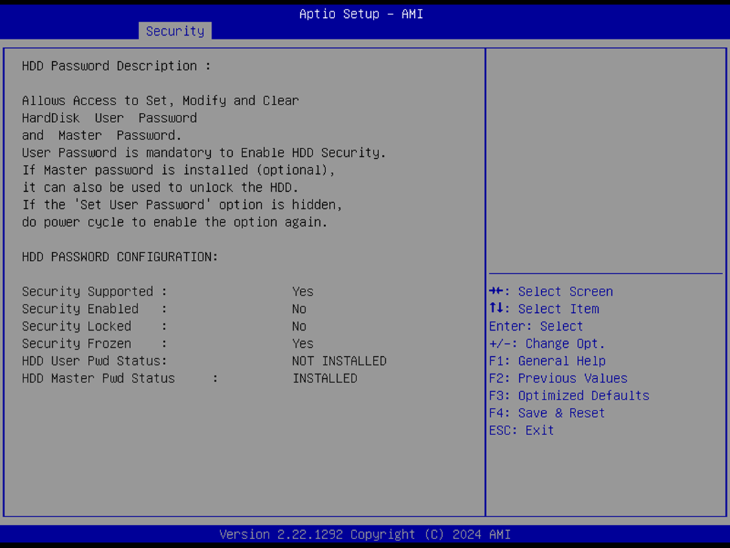
This submenu configures password protection for hard disk drives.
Set User Password
Sets a user password for the selected HDD.
⚠️ After setting or removing HDD passwords, a full power cycle is recommended. Changes made here are independent of BIOS save/discard actions. If this field becomes hidden, perform a power cycle to restore visibility.
Secure Boot
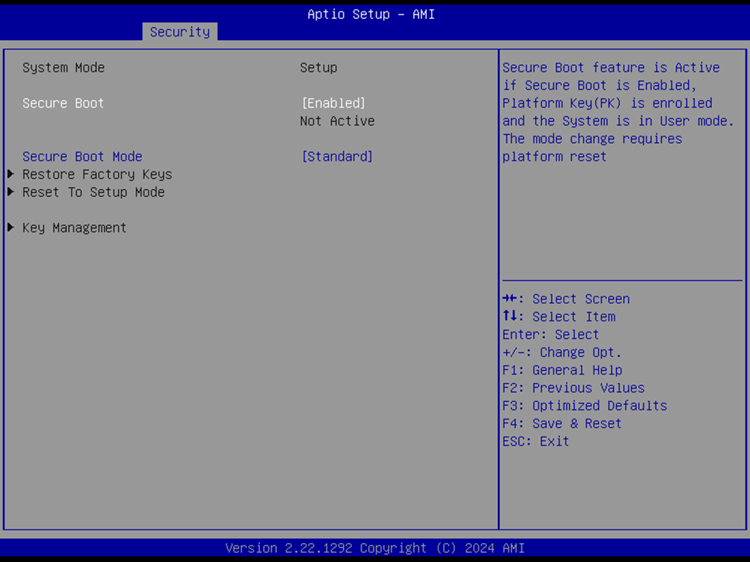
The Secure Boot feature ensures that only trusted operating systems and software are loaded during startup.
Secure Boot
Default:
EnabledOptions:
Enabled,DisabledWhen enabled, Secure Boot is active if a Platform Key (PK) is enrolled and the system is in User Mode.
Mode changes require a platform reset.
Secure Boot Mode
Default:
StandardOptions:
Standard,CustomIn Standard mode, keys and policies follow default specifications.
In Custom mode, policy variables can be modified by a physically present user without full authentication.
Restore Factory Keys
Restores factory default Secure Boot key databases and forces system into User Mode.
Reset to Setup Mode
Deletes all Secure Boot key databases from NVRAM.
Key Management
Opens advanced Secure Boot key management options.
Press Enter to access submenu.
Key Management
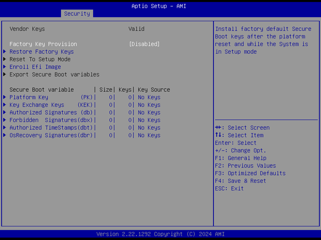
The Key Management submenu provides expert-level control over Secure Boot certificates and key databases.
Factory Key Provision
Default:
DisabledOptions:
Enabled,DisabledInstalls factory default Secure Boot keys after platform reset when in Setup Mode.
Restore Factory Keys
Reinstalls all factory Secure Boot keys and switches system to User Mode.
Reset to Setup Mode
Clears all Secure Boot key databases from NVRAM.
Enroll EFI Image
Allows SHA256 hash of a PE image to be enrolled into the authorized signature database (db) to permit its execution under Secure Boot.
Export Secure Boot Variables
Saves the content of current Secure Boot variables from NVRAM to a file.
Key Databases
Each item below shows key size, count, and source. All support Factory, Modified, or Mixed key sources.
Press Enter to manage entries in their respective sub-menus.
Platform Key (PK)
Default:
Size: 0, Keys: 0, Key Source: No Keys
Key Exchange Keys (KEK)
Default:
Size: 0, Keys: 0, Key Source: No Keys
Authorized Signatures (db)
Default:
Size: 0, Keys: 0, Key Source: No Keys
Forbidden Signatures (dbx)
Default:
Size: 0, Keys: 0, Key Source: No Keys
Authorized TimeStamps (dbt)
Default:
Size: 0, Keys: 0, Key Source: No Keys
OS Recovery Signatures (dbr)
Default:
Size: 0, Keys: 0, Key Source: No Keys
Each key field accepts:
Public Key Certificates:
EFI_SIGNATURE_LIST
EFI_CERT_X509 (DER)
EFI_CERT_RSA2048 (bin)
EFI_CERT_SHAXXXAuthenticated UEFI Variable
EFI PE/COFF Image (SHA256)
BIOS Update
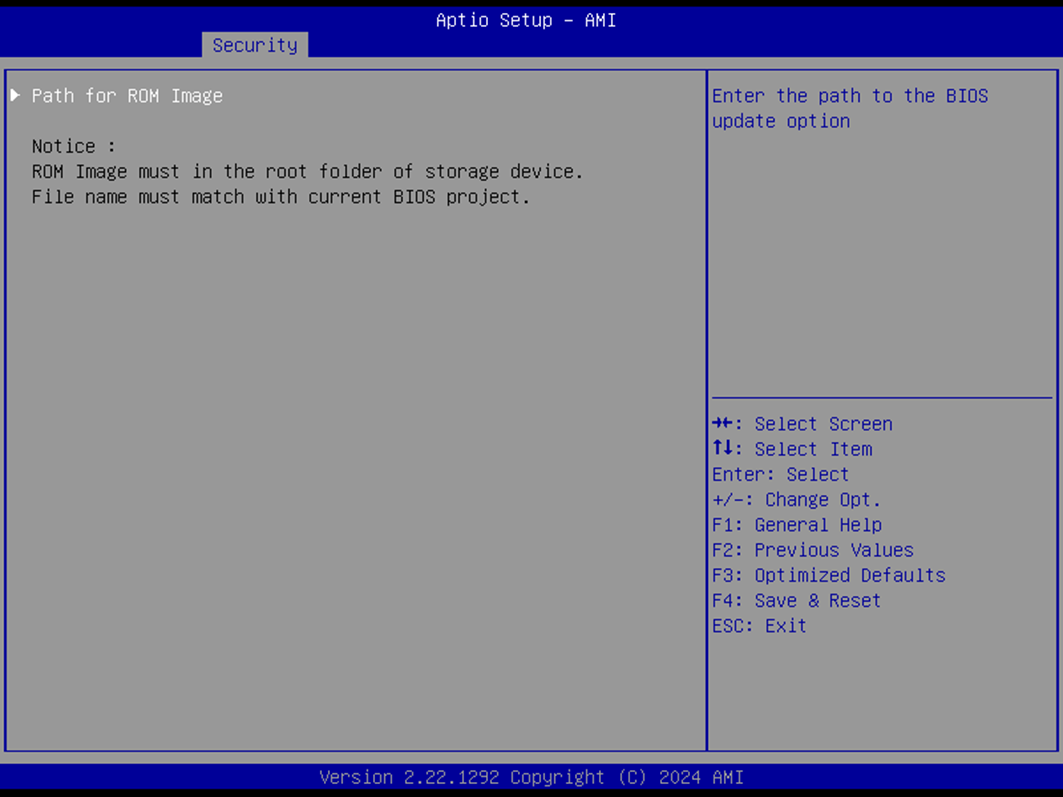
The BIOS Update submenu allows users to specify the file path to a BIOS ROM image for updating firmware.
Path for ROM Image
Enter the location or path of the BIOS update file to initiate the update process.
Boot Page
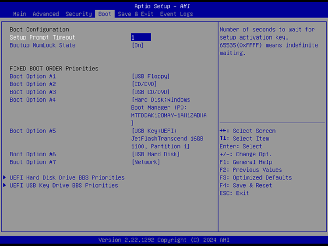
The Boot Page allows configuring boot behavior, NumLock state, and boot priority order.
Boot Settings
Setup Prompt Timeout
Default:
1Range:
1–65535Sets the number of seconds to wait for setup activation key.
65535(0xFFFF) means indefinite wait.
Bootup NumLock State
Default:
OnOptions:
On,OffSets the keyboard NumLock state at boot.
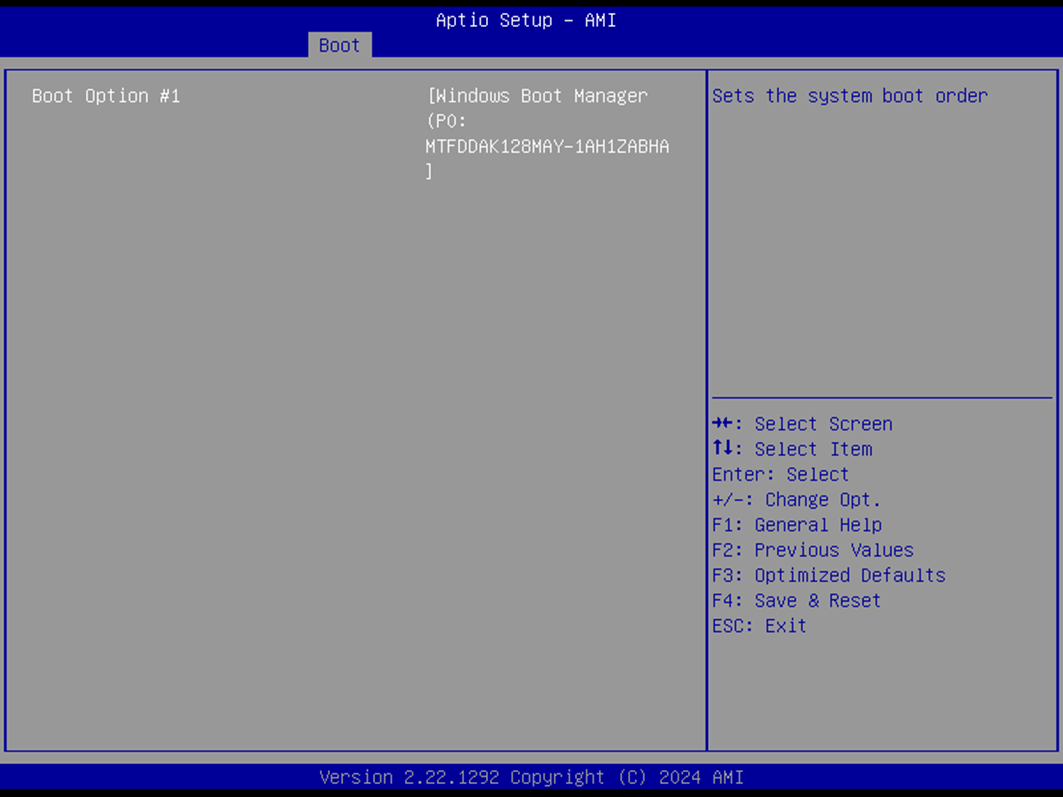
Boot Options
Boot Option #1 – #7
Default Values:
#1:
USB Floppy#2:
CD/DVD#3:
USB CD/DVD#4:
Hard Disk#5:
USB Key#6:
USB Hard Disk#7:
Network
Options:
USB Floppy,CD/DVD,USB CD/DVD,Hard Disk,USB Key,USB Hard Disk,Network,DisabledDefines the system boot sequence. Lower numbers indicate higher priority.
UEFI BBS Priorities
The following submenus allow ordering of UEFI-compatible boot devices within their respective types:
(UEFI) USB Floppy Drive BBS Priorities
(UEFI) CDROM/DVD Drive BBS Priorities
(UEFI) USB CDROM/DVD ROM Drive BBS Priorities
(UEFI) Hard Disk Drive BBS Priorities
(UEFI) USB Key Drive BBS Priorities
(UEFI) USB Hard Disk Drive BBS Priorities
(UEFI) Network Drive BBS Priorities
Press Enter to access each submenu and define device-specific boot priorities.
Drive BBS Priorities
This submenu appears per device type (USB, CD/DVD, HDD, etc.) and allows granular boot ordering for matching devices.
Boot Option #1
Options:
<Device Name>orDisabledSets boot priority for available devices of the selected type.
Save & Exit Page
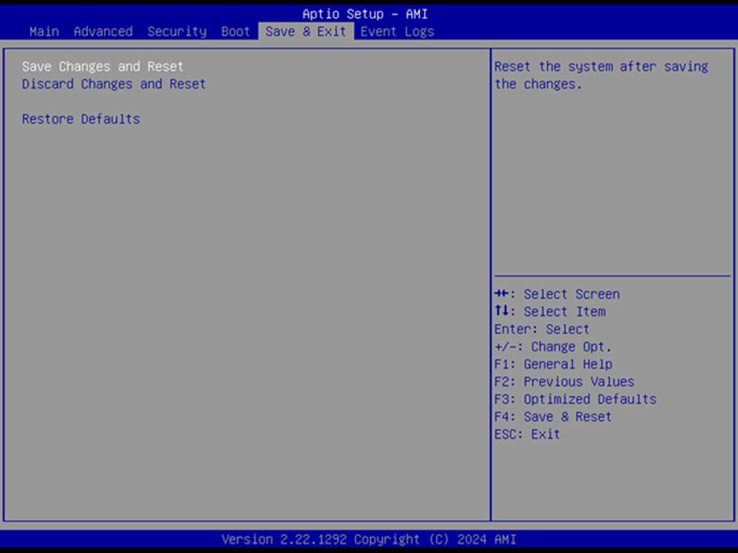
The Save & Exit Page provides options for applying or discarding changes and restoring factory defaults.
Save Changes and Reset
Saves BIOS configuration changes and restarts the system.
Discard Changes and Reset
Restarts the system without saving any changes.
Restore Defaults
Restores all BIOS settings to their factory default values.
Event Logs
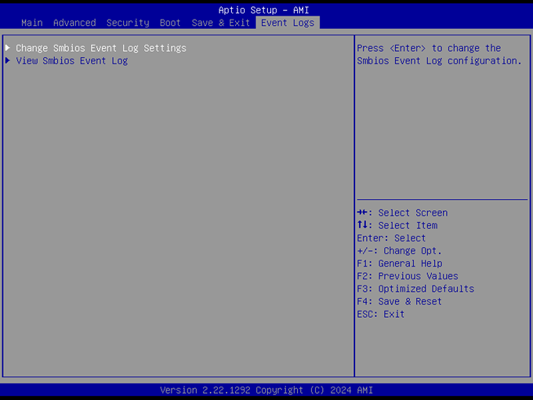
The Event Logs section allows you to configure and view SMBIOS event logging activity.
Event Log Options
Change SMBIOS Event Log Settings
Press Enter to configure logging behavior.
Opens the associated submenu.
View SMBIOS Event Log
Press Enter to view recorded SMBIOS event entries.
Opens the associated submenu.
Change SMBIOS Event Log Settings
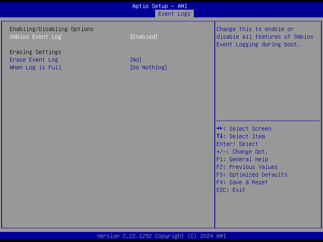
This submenu controls whether SMBIOS events are logged and how logs are handled.
SMBIOS Event Log
Default:
EnabledOptions:
Enabled,DisabledEnables or disables event logging during boot.
Erase Event Log
Default:
NoOptions:
NoYes, Next resetYes, Every reset
Determines if/when the event log should be cleared.
When Log is Full
Default:
Do NothingOptions:
Do NothingErase Immediately
Defines the system’s behavior when the event log reaches capacity.
View SMBIOS Event Log
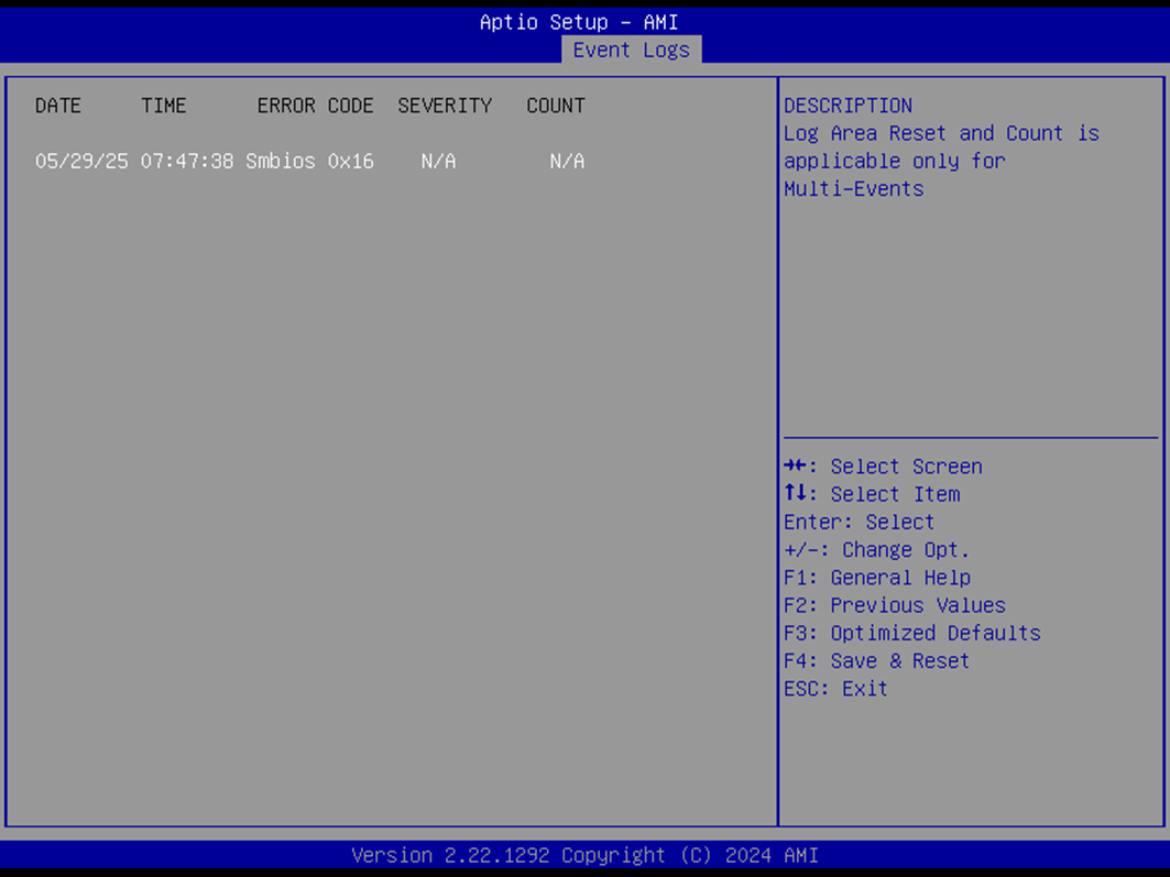
Displays recorded SMBIOS events with date, time, error code, severity, and count.
DATE / TIME / ERROR CODE / SEVERITY / COUNT
Example Entry:
MM/DD/YY HH:MM:SS Smbios 0x16 N/A N/AEvents are listed in chronological order.